Azteeg X3 Help - or "Where's Roy?" ;-)
18 posts
• Page 2 of 2 • 1, 2
Re: Azteeg X3 Help - or "Where's Roy?" ;-)
![]() by SystemsGuy » Thu Apr 11, 2013 12:49 pm
by SystemsGuy » Thu Apr 11, 2013 12:49 pm
Ok, got the extra low power mosfet's working, but still can't figure out the damned 1.1 shield. It simply should not be this hard! 
- SystemsGuy
- Posts: 250
- Joined: Sat Dec 29, 2012 7:44 am
Re: Azteeg X3 Help - or "Where's Roy?" ;-)
![]() by orcinus » Thu Apr 11, 2013 10:12 pm
by orcinus » Thu Apr 11, 2013 10:12 pm
The shield connects to J11 and, what, EXP2?
J11 is D41, D40, D37 and D35. EXP2 is D66 (A12), D65 (A11), D59 (A5), D58 (A4), D31 and D32.
Try tracing the signals from those to the MOSFETs, ADCs etc. on the shield, then (re)configure them in pins.h.
I don't think any of the firmwares supports more than 5 stepper drivers, though.
J11 is D41, D40, D37 and D35. EXP2 is D66 (A12), D65 (A11), D59 (A5), D58 (A4), D31 and D32.
Try tracing the signals from those to the MOSFETs, ADCs etc. on the shield, then (re)configure them in pins.h.
I don't think any of the firmwares supports more than 5 stepper drivers, though.
- orcinus
- Posts: 720
- Joined: Tue Feb 14, 2012 4:03 am
Re: Azteeg X3 Help - or "Where's Roy?" ;-)
![]() by SystemsGuy » Fri Apr 12, 2013 8:53 am
by SystemsGuy » Fri Apr 12, 2013 8:53 am
I'm not next to my printer Orcinus, but I think its' connected to one other as well. As an FYI, Marlin supports 6 out of the box - but in a deceptive way - Z can be configured with two motors, each with their own driver. I've honestly not seen a huge need to do this.
orcinus wrote:The shield connects to J11 and, what, EXP2?
J11 is D41, D40, D37 and D35. EXP2 is D66 (A12), D65 (A11), D59 (A5), D58 (A4), D31 and D32.
Try tracing the signals from those to the MOSFETs, ADCs etc. on the shield, then (re)configure them in pins.h.
I don't think any of the firmwares supports more than 5 stepper drivers, though.
- SystemsGuy
- Posts: 250
- Joined: Sat Dec 29, 2012 7:44 am
Re: Azteeg X3 Help - or "Where's Roy?" ;-)
![]() by Wired1 » Thu Apr 18, 2013 8:24 pm
by Wired1 » Thu Apr 18, 2013 8:24 pm
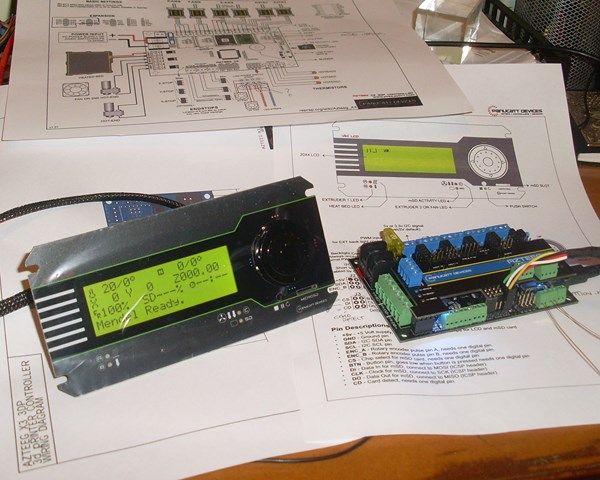
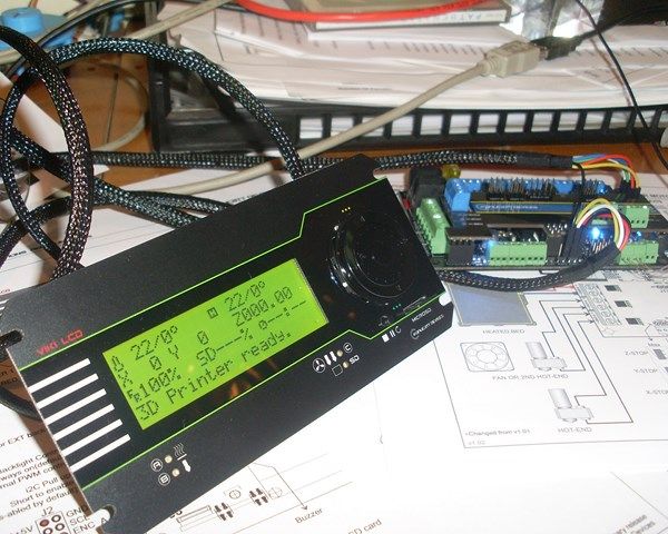
I'm not as far along this path as some of you guys so please excuse the noob. After a lot of searching for pin inromation I have connected the Viki to the Azteeg X3 via the I2C cables and uploaded the Marlin with I2C LCD support. I got one of the first Vikis and it came with two 6-pin leads of which I am so far only using one for power and I2C.
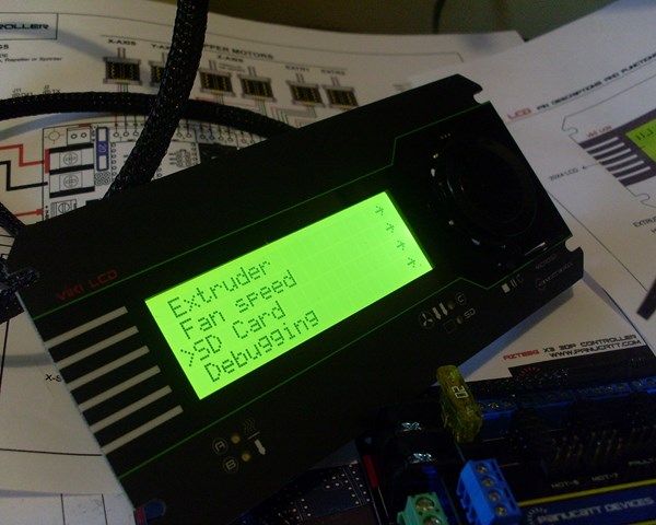
When it is running I have the display as shown and the first menu page when the right button or the middle button on the encoder are pressed. The rest of the buttons do nothing.
I am guessing I need to attach the leads from the other 6-pin lead to various places on the Azteeg but cannot find any information about where they should be connected. It looks like they are for the reset button plus the SD card stuff but like I say, the pinouts on the Azteeg are not published so short of tracing the pcb tracks it is a needle in a haystack scenario.
My initial questions are where should I attach the remaining leads from the Viki to the Azteeg X3? (I have the latest version), and which version of Marlin should I use to have all the functions working on the Viki panel?
Any help would be great thanks.
- Wired1
- Posts: 10
- Joined: Thu Apr 18, 2013 5:32 am
Re: Azteeg X3 Help - or "Where's Roy?" ;-)
![]() by SystemsGuy » Thu Apr 18, 2013 10:29 pm
by SystemsGuy » Thu Apr 18, 2013 10:29 pm
Sure - Steve Graber posted some pictures and details on the Delta forum here. https://groups.google.com/forum/?fromgr ... tGwtHNU0AJ
Getting software to work is a bit more challenging. The original lincomatic patches no longer merge into Marlin, and the one wolfmanjm did last week is now broken as well. Good news is he's on it, and I hope to have a working merge later tonight - if so I'll post that up here.
Getting software to work is a bit more challenging. The original lincomatic patches no longer merge into Marlin, and the one wolfmanjm did last week is now broken as well. Good news is he's on it, and I hope to have a working merge later tonight - if so I'll post that up here.
- SystemsGuy
- Posts: 250
- Joined: Sat Dec 29, 2012 7:44 am
Re: Azteeg X3 Help - or "Where's Roy?" ;-)
![]() by Wired1 » Thu Apr 18, 2013 11:18 pm
by Wired1 » Thu Apr 18, 2013 11:18 pm
Thanks, I had already found that one. The I2C is labelled and works the LCD straight away, it's the rotary selesctor and all the SD card stuff that has me beat at the mo. There are two of the three selector switch wires in that block plus another one on the second block not mentioned in that post. They all need digital inputs as well as the SD card and there are a dozen or so spare ones on the Azteeg so it's just a question of knowing which ones the Marlin has been adapted to use. There is also something needed to make the SD card work on the viki and a link to be removed or added on the azteeg to disable the azteeg SD and enable the viki one.
I think I'll try Repetier firmware as it looks to be a bit better developed with the Viki in mind.
What I really need is for Roy to produce a simple diagram showing how to attach the 12 wires from the Viki to on the Azteeg X3, they made both of them after all.
I think I'll try Repetier firmware as it looks to be a bit better developed with the Viki in mind.
What I really need is for Roy to produce a simple diagram showing how to attach the 12 wires from the Viki to on the Azteeg X3, they made both of them after all.
- Wired1
- Posts: 10
- Joined: Thu Apr 18, 2013 5:32 am
Re: Azteeg X3 Help - or "Where's Roy?" ;-)
![]() by Wired1 » Fri Apr 19, 2013 10:32 pm
by Wired1 » Fri Apr 19, 2013 10:32 pm
I posted this update on the reprap forum this morning but as many reading this may not use that forum I'll copy it here in the hope someone may be able to contribute:
OK some success, I'll post what I've got in the hope that someone else can fill in the blanks. I have now gone over to the dark side and used Repetier firmware which is not ideal as it works strangely with Pronterface. But the aim is to have a stand-alone machine that doesn't need a computer tethered to it so it really doesn't matter as long as it works. With Repetier the panel works with all the lights and the rotary switch selecting etc. and the LCD works of course.
On the back of the Viki there are two 6-pin headers, one for the I2C and the other for the SD card. My Viki came with two 6-pin to 6 individual pin fly leads so I plugged one into each header with the 6-pin blocks at the Viki end thus:
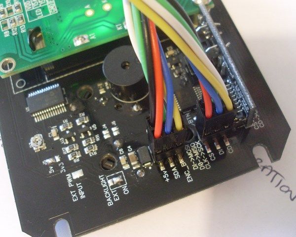
You can see I lined up the red wire in each onto the same corner as in the case of the left hand one (as per the photo) that is +5volts.
The Azteeg X3 has lots of places to attach the other end of these leads so first up I worked on the I2C as I knew this ran the LCD display and suspected it did a few other things too. It turns out that all the indicator lights, the selector switch and the LCD all run on the I2C bus. the only things that don't are the pause/run switch below the rotary switch, and the SD card stuff.
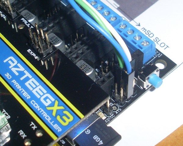
So taking the lead that runs from the left hand 6-pin header on the Viki (the one that has +5v on the corner pin) this goes to Exp3 header on the Azteeg X3. This connects as per this photo below, and if your lead matches mine would be like this:
Green @ @ Blue
Yellow @ @ Red
White @ @ Black
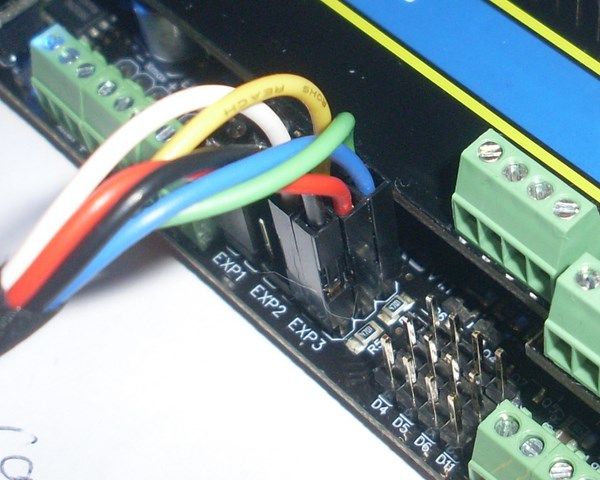
The position of the Yellow and White leads determines which way the rotary encoder works so if you want your encoder to go down the menu with a clock-wise rotation then do it the way I did.
Less obvious is the SD card connections and I still haven't gotten this working, however I have made some headway with the Azteeg pinout of the ICSP header. This header has clock, data in and data out as well as a reset button plus +5v and Gnd as per this layout (looking at the header on the back of the board with the dot top left):
MISO (DO) @ @ +5v
SCK (CLK) @ @ MOSI (DI)
RESET @ @ GND
So I have connected the second lead from the Viki (the right hand one in the photo above) like this:
White @ @ NC
Green @ @ Blue
NC @ @ NC
So that leaves three wires that want digital inputs to attch to for the run/pause switch, card detect and chip select. I have tried a random selection of available pins for these and so far not had any success. These pins are probably assigned somewhere in Repetier but I haven't found the reference yet. You can connect the black wire to the reset button if you want a reset button on the viki panel but personally it is too close to the rotary encoder for my liking and easily hit by mistake.
I also think there may be a hardware link to add or remove somewhere on the Azteeg X3 to force it to look at the remote SD card as it seems odd to have two SD card slots otherwise. There is no documentation to show this of course.
OK some success, I'll post what I've got in the hope that someone else can fill in the blanks. I have now gone over to the dark side and used Repetier firmware which is not ideal as it works strangely with Pronterface. But the aim is to have a stand-alone machine that doesn't need a computer tethered to it so it really doesn't matter as long as it works. With Repetier the panel works with all the lights and the rotary switch selecting etc. and the LCD works of course.
On the back of the Viki there are two 6-pin headers, one for the I2C and the other for the SD card. My Viki came with two 6-pin to 6 individual pin fly leads so I plugged one into each header with the 6-pin blocks at the Viki end thus:
You can see I lined up the red wire in each onto the same corner as in the case of the left hand one (as per the photo) that is +5volts.
The Azteeg X3 has lots of places to attach the other end of these leads so first up I worked on the I2C as I knew this ran the LCD display and suspected it did a few other things too. It turns out that all the indicator lights, the selector switch and the LCD all run on the I2C bus. the only things that don't are the pause/run switch below the rotary switch, and the SD card stuff.
So taking the lead that runs from the left hand 6-pin header on the Viki (the one that has +5v on the corner pin) this goes to Exp3 header on the Azteeg X3. This connects as per this photo below, and if your lead matches mine would be like this:
Green @ @ Blue
Yellow @ @ Red
White @ @ Black
The position of the Yellow and White leads determines which way the rotary encoder works so if you want your encoder to go down the menu with a clock-wise rotation then do it the way I did.
Less obvious is the SD card connections and I still haven't gotten this working, however I have made some headway with the Azteeg pinout of the ICSP header. This header has clock, data in and data out as well as a reset button plus +5v and Gnd as per this layout (looking at the header on the back of the board with the dot top left):
MISO (DO) @ @ +5v
SCK (CLK) @ @ MOSI (DI)
RESET @ @ GND
So I have connected the second lead from the Viki (the right hand one in the photo above) like this:
White @ @ NC
Green @ @ Blue
NC @ @ NC
So that leaves three wires that want digital inputs to attch to for the run/pause switch, card detect and chip select. I have tried a random selection of available pins for these and so far not had any success. These pins are probably assigned somewhere in Repetier but I haven't found the reference yet. You can connect the black wire to the reset button if you want a reset button on the viki panel but personally it is too close to the rotary encoder for my liking and easily hit by mistake.
I also think there may be a hardware link to add or remove somewhere on the Azteeg X3 to force it to look at the remote SD card as it seems odd to have two SD card slots otherwise. There is no documentation to show this of course.
- Wired1
- Posts: 10
- Joined: Thu Apr 18, 2013 5:32 am
Re: Azteeg X3 Help - or "Where's Roy?" ;-)
![]() by Wired1 » Sat Apr 20, 2013 12:43 pm
by Wired1 » Sat Apr 20, 2013 12:43 pm
OK i have it working now, in Marlin. Full control from the Viki including SD card, plus it all still works from Pronterface as a bonus.
I tried uploading it to github but I can't figure out how you do that so if anyone wants it you'd better PM me with your email address and I'll email you a copy. It is 1.5Mb as a zipped up file.
You need to use Arduino 0023 (http://arduino.cc/en/Main/Software), install instructions are as per the original for the Azteeg (http://reprap.org/wiki/Azteeg_X1)
This uses the LiquidTWI2 library v1.2.3 or later ( https://github.com/lincomatic/LiquidTWI2 ).
Make sure the LiquidTWI2 directory is placed in the Arduino or Sketchbook libraries subdirectory.
Harware connections and mods: Marlin configured for Viki LCD panel on an Azteeg X3.
Latest version set up to work straight out of the box with the Viki panel on an Azteeg X3.
Uses the SD card on the Viki panel. Connect the two 6-pin to 6 loose pin plugs to the two headers on the back of the VIki panel.
The loose end of the I2C header on the Viki connects to EXP3 on the Azteeg X3 as per the diagram http://files.panucatt.com/datasheets/x3 ... iagram.pdf.
The loose end of the other header connects to three pins of the ICSP header on the X3 (refer to the above diagram again) as follows:
Viki DI -> Azteeg MOSI, Viki DO -> Azteeg MISO & Viki CLK -> Azteeg SCK
Viki CD -> Azteeg D49 & Viki CS -> Azteeg D53 (both below the ICSP header and next to the Azteeg SD card holder.
The remaining lead from the SD header on the Viki BTN is connected to Azteeg D32 which is on EXP2.
In addition to this you need to remove the soldered link J12 on the reverse of the Azteeg X3 to disable the SD reader on the control board and enable the one on the Viki panel.
- Wired1
- Posts: 10
- Joined: Thu Apr 18, 2013 5:32 am
18 posts
• Page 2 of 2 • 1, 2
Return to 3D Printer General Discussion
Who is online
Users browsing this forum: No registered users and 19 guests